Table Of Content
To connect, strip back the insulation from the ends of the wires, hold them between your fingers and twist the wire nut in a clockwise direction onto the ends. D1's bottom half is controlled by a different switch -- at C1. D1 has received neutral and constant hot from D2, but for C1 to switch D2's bottom half, the white wire from D1 to C1 must take hotness to C1, so the C1 switch can send hotness or deadness back to D1's bottom half. The hot-side terminal tab of D1 must be broken away to prevent the bottom half from being hot all the time (unswitchable). In this article, we will talk about the various aspects of a basic house wiring diagram.
The Electrical Upgrade - Soundings Magazine
The Electrical Upgrade.
Posted: Mon, 14 Nov 2022 08:00:00 GMT [source]
Standard Home Wiring Diagram Symbols
You will want to refer to it oftenas you work on your project. Once the electrical project is completed the diagram will be useful for testing and troubleshooting the circuit. A wiring diagram distills complex information into an easy-to-follow visual graphic.
Volt Circuits
How to Identify Potential Outlet Wiring Problems where Space Heaters are Used, Fix Electric Outlet Problems Caused by Portable Space Heaters.
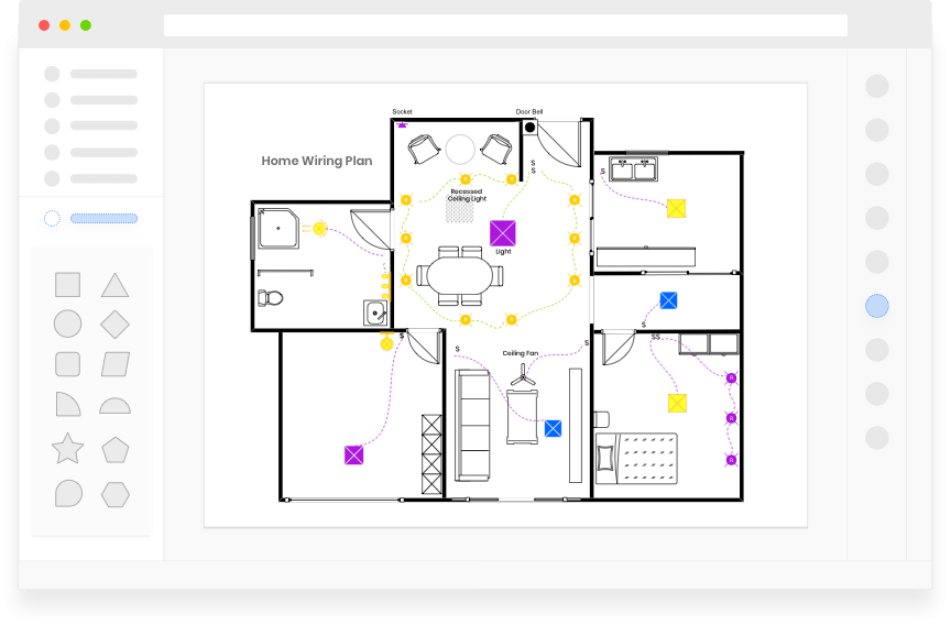
Kitchen Electrical Wiring Diagram
Your entire team can share in the creation of any wiring diagram when necessary. Just save your diagram to a shared folder and leave comments and feedback as appropriate. It's easy to remain on the same page, when SmartDraw works how you work. You can easily pick up the discussion where you already communicate with your team including Microsoft Teams®, Slack and Confluence. The hot wire carries power from the panel to the device you are wiring.
Components of a House Wiring Diagram
A receptacle wiring diagram features pictures or line drawings of the receptacle and the power supply wires. It shows the installer exactly where on the receptacle to attach the hot, neutral and ground electrical wires. In house wiring, a circuit usually indicates a group of lights or receptacles connected along such a path. Each circuit can be traced from its beginning in the service panel or subpanel through various receptacles, fixtures, and/or appliances and back. Some of the most common electrical projects that a homeowner will encounter are replacing light switches and wall outlets. Room additions or major renovations may even involve having to increase the number of wall outlets in a particular area of your home.

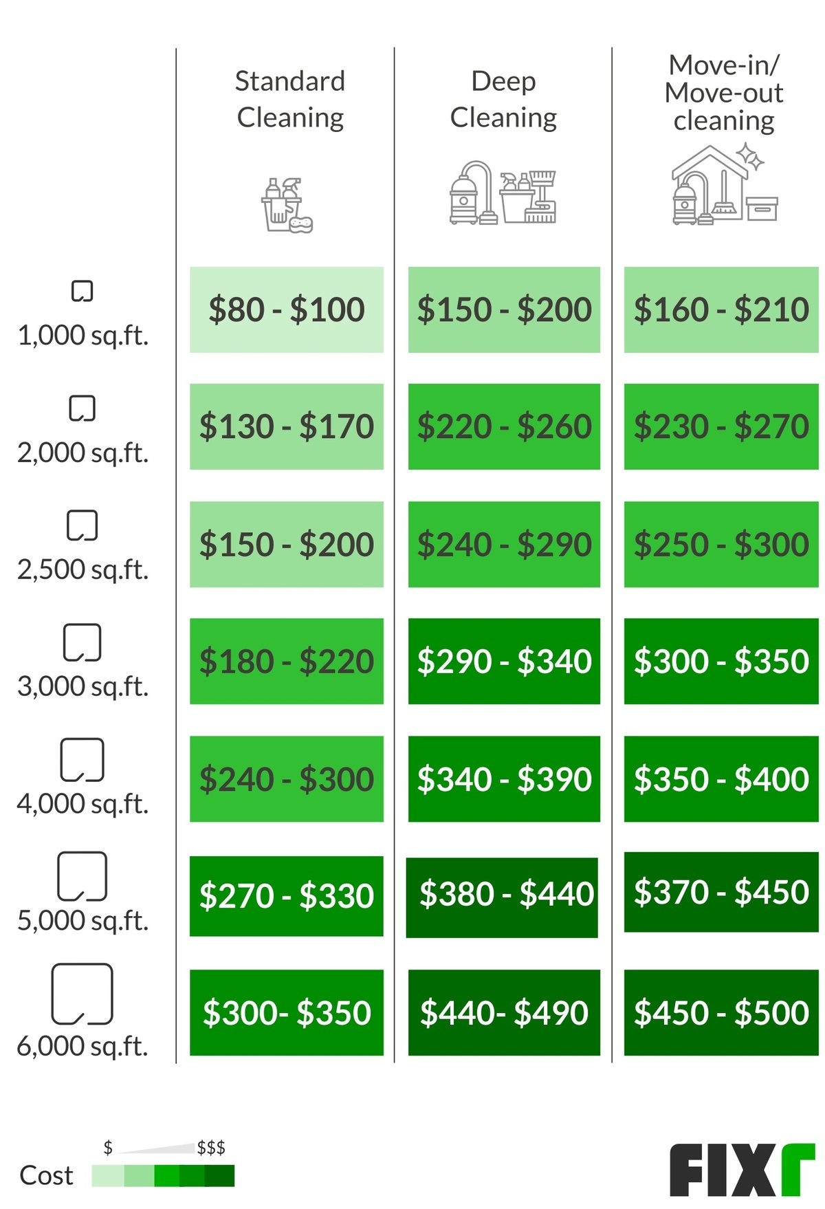
Electrical wire and circuit breakers are designed to work in tandem with one another, and each must be of a proper corresponding size. For example, 14/2 gauge electrical wire is rated to a maximum of 15 amps and should not be used with any circuit breaker larger than 15 amps.12/2 gauge wiring is rated to a maximum of 20 amps. These two size wires are the standard that are used in homes today for most lighting and wall outlets. Again, heavier gauges and higher amp circuit breakers must be used for certain appliances that use more electricity and as dictated by local and state building codes. A single-phase house wiring diagram depicts the layout and components of a single-phase circuit.
It can help them to avoid sharp places, open live wires, and many other such scenarios. An injury would mean time delay as well as an expensive hospital bill. A House Wiring Diagram thus also serves as the safest medical treatment for such cases.
Therefore, the scope of this article will be confined to the most basic of electrical jobs using only single-pole switches and end-of-run receptacles. A6 will power our last two sub-branches of the whole circuit. This scenario is similar to the one just described for A5 sending power through light and switch boxes B5 and C5. In this case, however, power from A6 reaches the switchbox first, rather than the light box. Comparing the diagrams of the two switchboxes and the two light boxes, they are identical.
Residential Electrical Wiring
In this section, we are going to take a look at three examples of house wiring diagrams, for the bedroom, bathroom, and basement of a house. Whenever working with electrical systems, we are all taught to look out for your safety. Injuries can happen anywhere, anytime, and due to many reasons. A useful house wiring diagram can show electricians where the points of damage lie in the whole network.
Other than these 20 symbols, there are some lighting, electrical and telecom, and wall, shell or structure symbols that are involved in a house wiring diagram. One wire is attached to each brass screw on the right-hand side of the switch. Wiring diagrams use an array of special symbols that represent various circuit elements like, switches, bulbs, electric outlets, breakers, smoke detectors, and many more. If the improper gauge wire is used with the wrong size circuit breaker, it can easily result in a fire or a malfunctioning electrical circuit.
Due to the separation between floor and the rental possibility this project was just like wiring two homes because there were separate services for furnaces, air conditioners etc. Let’s say you want to install an movement sensor to turn off the lights and air conditioning when you’re not home. It might have six or more wires sticking out of it when you pull it out of the box. 2 Identify any large, double (240-volt) circuit breakers first.
It looked like a jumble of spaghetti, with square meatballs. Share your wiring diagram with anyone, even if they don't own a copy of SmartDraw, with a link. You can also easily export any diagram as a PDF or common image formats like PNG or SVG. Having a map of your home’s electrical circuits can help you identify the source of a problem. The red wire from C3 to D3 is hot or not, according to the switch C3, and this switchedness is passed on to D2's bottom half, as is D3's constant hot passed on to the upper half of D2. Electrical switch diagrams that are in color have an advantage over ones that are black and white only.
Without an adequate amount of wiring, you will need to buy more or wait for the new installation to be delivered. It can hamper the timeframe of the work, especially in big projects like that of an apartment building or a condominium. ASmartDraw gives you both wiring diagram templates and examples to help you get started. High-tech Electric Meters In the future, your electric meter may be able to sense power outages, detect wiring problems, monitor appliance efficiency, and send reports instantly to the power company. The company can then save you money by notifying you of problems or by remotely shutting down noncritical appliances during peak-rate hours.
To connect a switch, imagine a wire running from a “hot” junction point to the box that will contain the light switch. Another wire will lead from that light switch box to the junction box that contains the light fixture. The switch itself is what will connect these two wire runs and allow the electrical current to flow to the light or to be stopped at the switch. A house wiring diagram is a wiring diagram for any electric circuit in your home which is drawn most directly so that it can easily guide the electrician (or yourself) in case needed.
The wiring diagram shows where to connect each wire on the device. Wiring diagrams can also represent how electricity flows in a circuit. These diagrams show the power source and voltage, as well as the loads (lights and equipment) and any components that affect the flow of electricity, like switches. This type, called a schematic, is most often used by engineers and other electrical professionals. A professional house wiring diagram software effectively helps you create accurate and high-quality house wiring diagrams. If the circuit breakers aren’t already numbered inside the electrical panel, number them.