Table Of Content
A “hot” wire will come from a circuit breaker or other “hot” junction box and lead to the first wall outlet. From there another wire is run from the first wall outlet to the second wall outlet. This continues until the entire room has been hooked-up or until the maximum number of fixtures has been attached to a particular circuit.
Workshop Electrical Wiring Diagram
Look at the picture and find the wires coming off the device. The movement sensor will have some wires that go to a transformer, and others to HVAC equipment and lights. Wiring diagrams are often easier to interpret than written directions, especially for people unfamiliar with electrical systems and concepts. If you can take your finger and trace a line from one place to another, you can follow a wiring diagram.
Push the Wires into the Box
Modern receptacles are called “duplex receptacles” because they have two screws on both sides. As the name implies, they can bring electrical current into one set of screws and then send it out on the other “duplex” set of screws to another fixture. Light switches and wall outlets have screws on both sides for connecting wires.
Electrical Wiring Symbols
Determine which major electrical appliance(s) it supplies by turning on each electrical appliance (don’t forget equipment such as the furnace and the pool pump) until you find the right one(s). Repeat with the other large circuit breakers and major appliances. 1 At the electrical panel, turn off all of the circuit breakers. Many states and local jurisdictions permit homeowners to perform their own electrical work, but some do not.
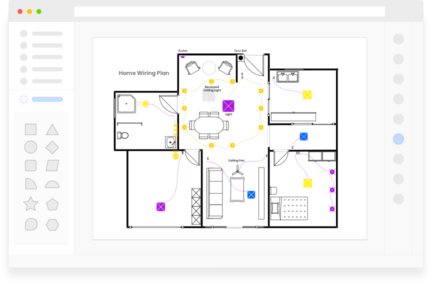
Gallant is meticulous in adhering to them, yet he often goes a step further to make his electrical systems even safer and easier to use. On the following pages, you’ll see the basics of wiring a house to meet code, along with a look at Gallant’s extras. It is the place where we go through the steps you need to take to create a house wiring diagram with EdrawMax. However, before we start, there are a few things you need to know about the interface. Homeowners doing DIY electrical work are most likely to go with basic wiring and pictorial diagrams, usually included in the instructions for electrical devices. This could be the power supply or the light or sensor that you’re installing.
This circuit starts with A4 receiving hot (black) and neutral (white) wires from the main electrical panel -- imagine the panel below the image. A4 passes hots and neutrals to nearby receptacles A3 and A5 by means of their wires' contact with the terminals on A4. A3 and A5 are the beginnings of the two main branches of this circuit, and we can identify several sub-branches that are developed beyond them.

The green screws are for the ground wires, the silver/stainless colored screws are for the white neutral wires and the brass colored screws are for the black “hot” wires. As we see in the following Basement Wiring Diagram, the square patterns are switches while the circular or rectangular patterns are light fixtures. A simple wiring diagram shows the connections in series and parallel for the various electrical appliances such as bulbs. Different sections colored in different colors here do not represent the color coding of wires.
Electrical - Need Part Number For Ac Wot Relay - StangNet.com
Electrical - Need Part Number For Ac Wot Relay.
Posted: Mon, 18 Jul 2016 07:00:00 GMT [source]
Make wiring diagrams, electrical circuit plans, schematics and more
The tiny xenon bulbs in the accent lights in the kitchen of the Charlestown, Mass., TV project produce an incredibly bright light, and they boast a 10,000-hour life span. Based on his tests, the handyman was right to figure something was wrong at C2 but wrong to assume that meant the switch was bad internally. That could have been true, but since I said he was wrong, you therefore know that the only other possibility would be the poor quality of C2's black-wire connection to the switch's "common" terminal. Since he only worked on changing C2's switch, he must have hooked the new one up wrong -- with the black on one of the traveler terminals (we don't know which one).
For example, if a wire of too small gauge is used with a high amp break, then the wire can overheat and catch fire long before the circuit breaker ever trips. On the other hand, if a too large of a gauge wire is used with a low amp breaker then the breaker may continuously trip, disrupting the circuit before the wire ever reaches its maximum electrical load. Arc-Fault Circuit Interrupters A conventional circuit breaker can’t detect the low-level arcing (a spark-generating short circuit) that can occur on frayed or cut wires. Arc-fault circuit interrupters (AFCIs), installed at the service panel, protect against such dangerous shorts and are now required in new bedroom circuits. Gallant first used them at the TV project in Billerica, Mass. Back at B5, hotness for the light comes back (or not) from switch C5 on the red.
It also helps in troubleshooting electrical issues by pinpointing the location of a problem.Additionally, a House Wiring Schematic Diagram provides convenience. Have you ever tripped a circuit breaker and had to search for the specific one to reset? With a diagram, you can easily locate the breaker and know which part of the house it controls. This saves time and eliminates guesswork.Moreover, the diagram serves as a future reference for any changes or upgrades in the electrical system. It promotes safety, convenience, and future planning, making it a valuable asset to every homeowner.
Diagrams showing electrical flow through a circuit use standardized symbols to represent electrical components. Ground is a vertical line with three successively smaller horizontal lines underneath. Switches are diagonal lines emanating from the line representing the electrical flow. But when I was a second-year apprentice and my foreman handed me a wiring diagram, I briefly panicked. I saw a bunch of boxes and a lot of seemingly randomly drawn lines.


No comments:
Post a Comment